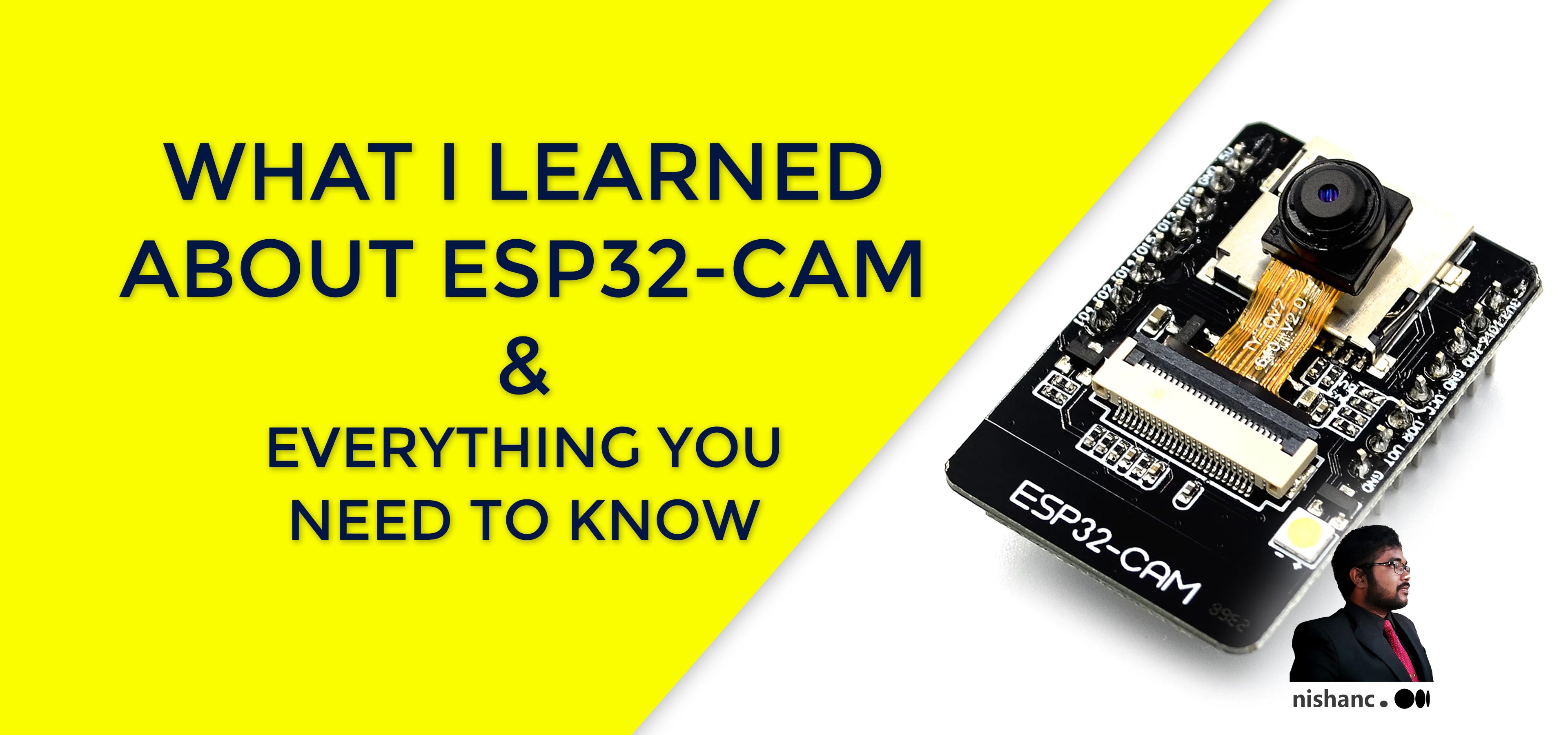
What I Learned About ESP32-CAM and Everything You Need to Know
I know that IoT is not my usual expertise, but as Alan Kay once said “People who are really serious about software should make their own hardware.” This little Wi-Fi enabled camera module (ESP32-CAM AI-THINKER) can add some value to your IoT projects, home automation and other pet projects that you’re curruntly working on so let’s jump right in.
Prologue
ESP32-CAM is a low-cost ESP32-based development board with onboard camera, small in size. It is an ideal solution for IoT application, prototypes constructions and DIY projects.
The board integrates WiFi, traditional Bluetooth and low power BLE , with 2 highperformance 32-bit LX6 CPUs. It adopts 7-stage pipeline architecture, on-chip sensor, Hall sensor, temperature sensor and so on, and its main frequency adjustment ranges from 80MHz to 240MHz.
Fully compliant with WiFi 802.11b/g/n/e/i and Bluetooth 4.2 standards, it can be used as a master mode to build an independent network controller, or as a slave to other host MCUs to add networking capabilities to existing devices.
It is suitable for home smart devices, industrial wireless control, wireless monitoring, QR wireless identification, wireless positioning system signals and other IoT applications. It is an ideal solution for IoT applications.


Before you buy!
When you go to buy this, the basic package is the development board + the camera module.

Built-in antena in the ESP32-CAM module is not powerfull enough if you’re planning to position it far away from the router, so you might want to buy an external antenna as well. (I got good results around 15–20 m without antenna).

If you decided to go with an external antenna, you need to unsolder antenna selection resistor and solder it again with a different orientation.
See this article from Random Nerd Tutorials to learn more. It is much easier than it looks because you don’t necessarily need to add the resistor as long as the pads are connected, so you can also drop some solder to connect those points and remove the resistor.
Note: ESP32-CAM AI-THINKER does not have a screen, microphone, motion sensors, battery connector, built-in programmer, grove connectors or function buttions so you have to find solutions to these if you need them.
Programmer
To program this you need to have either FTDI Programmer(USB To TTL Serial Converter) or an Arduino development board. Both programmers use Arduino IDE so you need to have that as well.
Program using Arduino (UNO)
Chances are that you have an Arduino lying around somewhere, so you don’t need any other programmers to do this. Connect them according to the following schematics and you should be good to go. Important: GPIO 0 needs to be connected to GND so that you’re able to upload code.

Program using FTDI Programmer
If you don’t have an ardunio and want something cheep, buy one of these. You have to connect your ESP32 CAM module to FTDI Programmer like below, Important: GPIO 0 needs to be connected to GND so that you’re able to upload code.
Many FTDI programmers have a jumper that allows you to select 3.3V or 5V. Make sure the jumper is in the right place to select 5V.
Uploading Code

Step 1: Download Arduino IDE
Step 2: In your Arduino IDE, go to File> Preferences
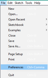
Step 3: Enter https://dl.espressif.com/dl/package_esp32_index.json,http://arduino.esp8266.com/stable/package_esp8266com_index.json into the “Additional Board Manager URLs” field as shown in the figure below. Then, click the “OK” button:

Step 4: Open the Boards Manager. Go to Tools > Board > Boards Manager…

Step 5: Search for ESP32 and press install button for the “ESP32 by Espressif Systems“:
Step 6: Afther that you can set ESP32 Wrover Module as your board. Also set upload speed as 115200, Flash Frequency to 40MHz, Flash Mode to QIO, Partition Sceme to Huge App.

Step 7: After that you should be able to access ESP32 examples, open the Camera Web Server example as follows.
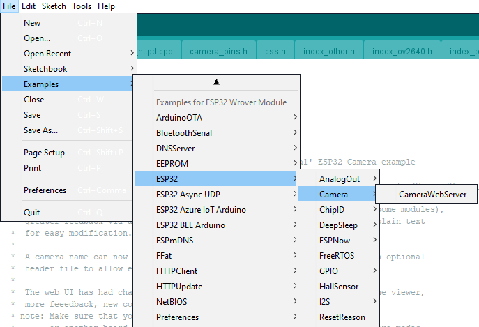
Or you can download more customizable version of the same exmple from here.
Once the Arduino IDE opens up source files, you need to make few changes.

Where it says “Select camera mode”, comment out everything and uncomment #define CAMERA_MODEL_AI_THINKER
And add ssid and password removing all the *s.
Now you can complile and upload your code. When you are uploading your code, some information will pop up in the output.

When it says connecting… it’s a good idea to press the reset button on the ESP32 CAM module if it takes a long time. Usually you don’t have to do this but in some cases I had to do it. So keep that in mind as well. Reset button is not so hard to locate because it is the only button on the board.

Once it’s uploaded, remove the connection between GPIO 0 and GND [Note: When you want to program it again, you should connect those pins again.]

Open Serial Monitor using Tools > Serial Monitor, Press Reset button once. If all went well, following output should show up.
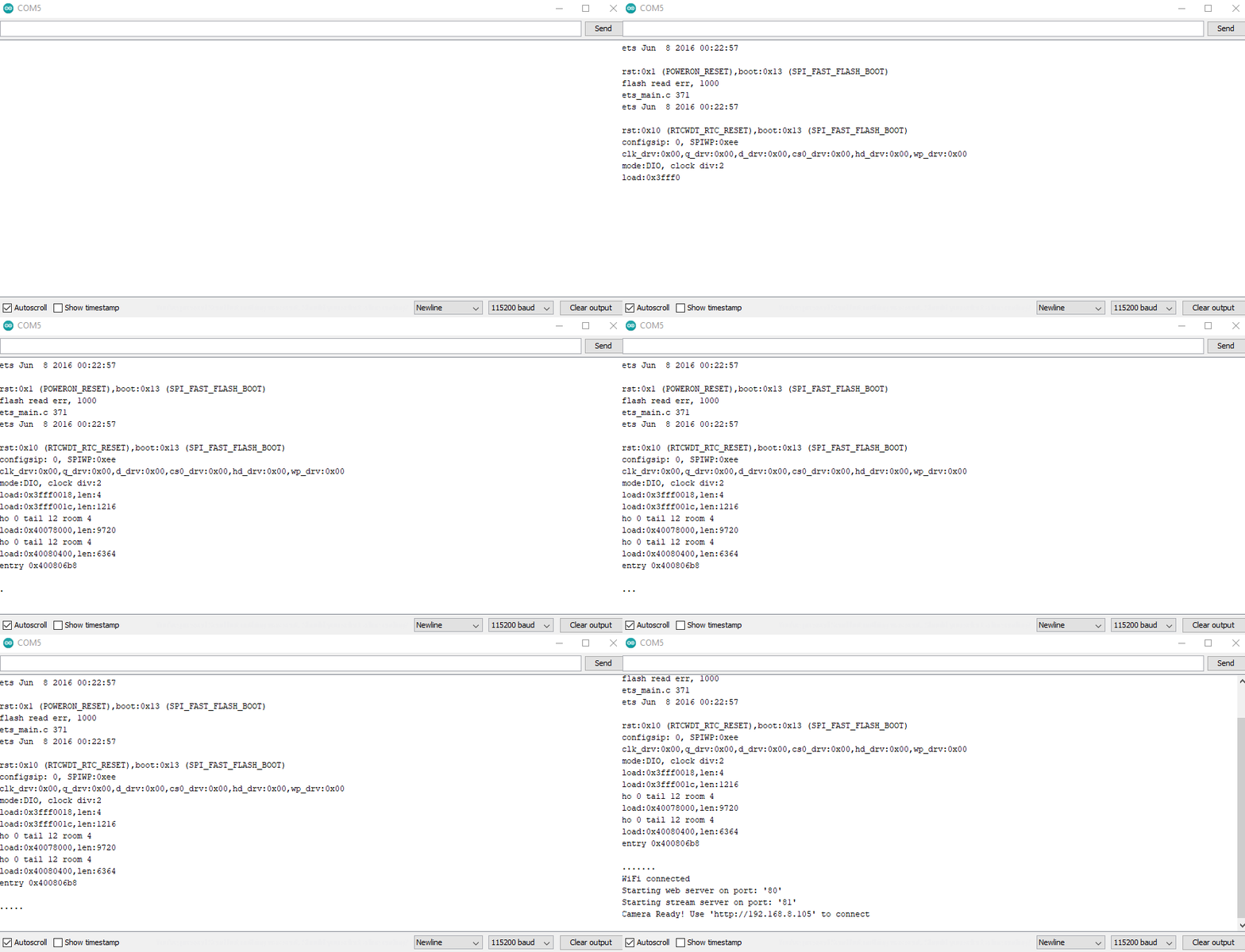
Which will give you an endpoint to navigate using a web browser.

Scroll down untill you see these 3 buttons,Click on ‘Start Stream’ to start the web server.

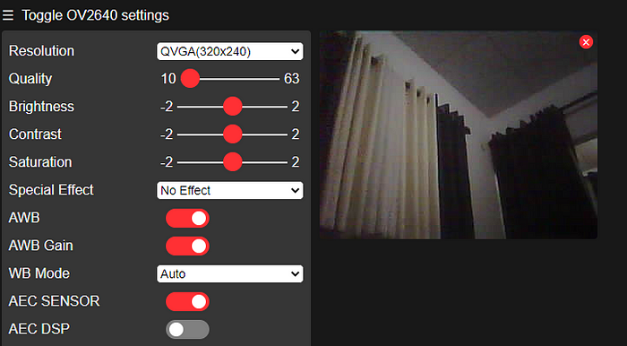
Nice. If you came this far the rest is nothing! Let’s see few things you can do to make this experience a little bit nicer.
Static IP address configuration
Arduino project with the changes I do here after can be found here.
You might have noticed that, this endpoint (IP address) you get chages every time when you power it up. That’s because your router assigns an IP address within the subnet which is curruntly available. In my case it can be between 192.168.8.100 to 192.168.8.105 depending on the devices connected in my house. So what you can do is tell the ESP32 specifically which IP address to use. You can select something like 192.168.8.110 (If you don’t have 10 devices connected to the internet) because that IP address will always be available.
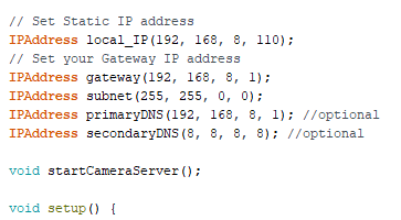
You can declare 5 IPAddress variables as above. To get gateway, subnet, dns, open Command Prompt and type “ipconfig /all” followed by Enter. Eventhough here it says promary DNS and secondary DNS are optional, you might want to add those because in the future you’re going to need it.
Scroll down until you see, WiFi.begin(ssid, password)
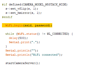
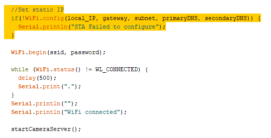
Add following lines before that.
  //Set static IP
  if(!WiFi.config(local_IP, gateway, subnet, primaryDNS, secondaryDNS)) {
    Serial.println("STA Failed to configure");
  }
Now you should be able navigate to http://192.168.8.110 everytime you power it up, without worrying about the IP address it got connected to.
But still you cannot access the video stream from anywhere on the earth. You need to be connected to your WiFi network. If you want to access this stream from outside your network, you might want to configure port forwading on your router or else you can use ngrok to create a real-time web UI where you can introspect all HTTP traffic running over this IP address. Take look at this to learn more.
Get SSID and Password from SD Card
If you have 2GB or 4GB Micro SD Card, you can insert that and read from / write to it.
Create two text documents as ssid.txt and password.txt inside the SD card. (there might be a way to do it using one file, but I prefer this way)
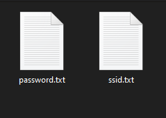
Add your SSID and Password to the first line of each file, save, then insert the SD card to ESP32 module.
On the arduino IDE comment out our original char variables for SSID/Password and declare two arrays with some fixed length (should be able to hold your SSID and password).

Now again before line WiFi.begin(ssid, password); we need read our SSID and Password from the text files. (Add #include “SD_MMC.h” to the top first.) Read more.
This will read and store ssid and password so in the future if your SSID or password changed, you don’t need to program the ESP32 again, just edit those 2 files in the sd card.
Save Images to SD Card
This will come in handy as well, since now you have free space on the SD card, we will save a snapshot every x second. For this step to work properly you need to have primary DNS and secondary DNS configured properly in the Static IP address configuration section.
First define few variables and include some header files.
Scroll down, after startCameraServer(); line, let’s check if we have internet and set system time zone, so we can add date and time as the file name of images. init_time() function is responsible for getting the time from an NTP server.
Change the time zone according to your area using setenv(); function. I am on Indian Standard Time. Take a look at here and here on how to use setenv(); to configure time zone.
In the loop() function, we will save a photo with date and time, if internet is not connected we’ll save it with a number.
Implement save_photo()
Implement save_photo_numbered(); and save_photo_dated();
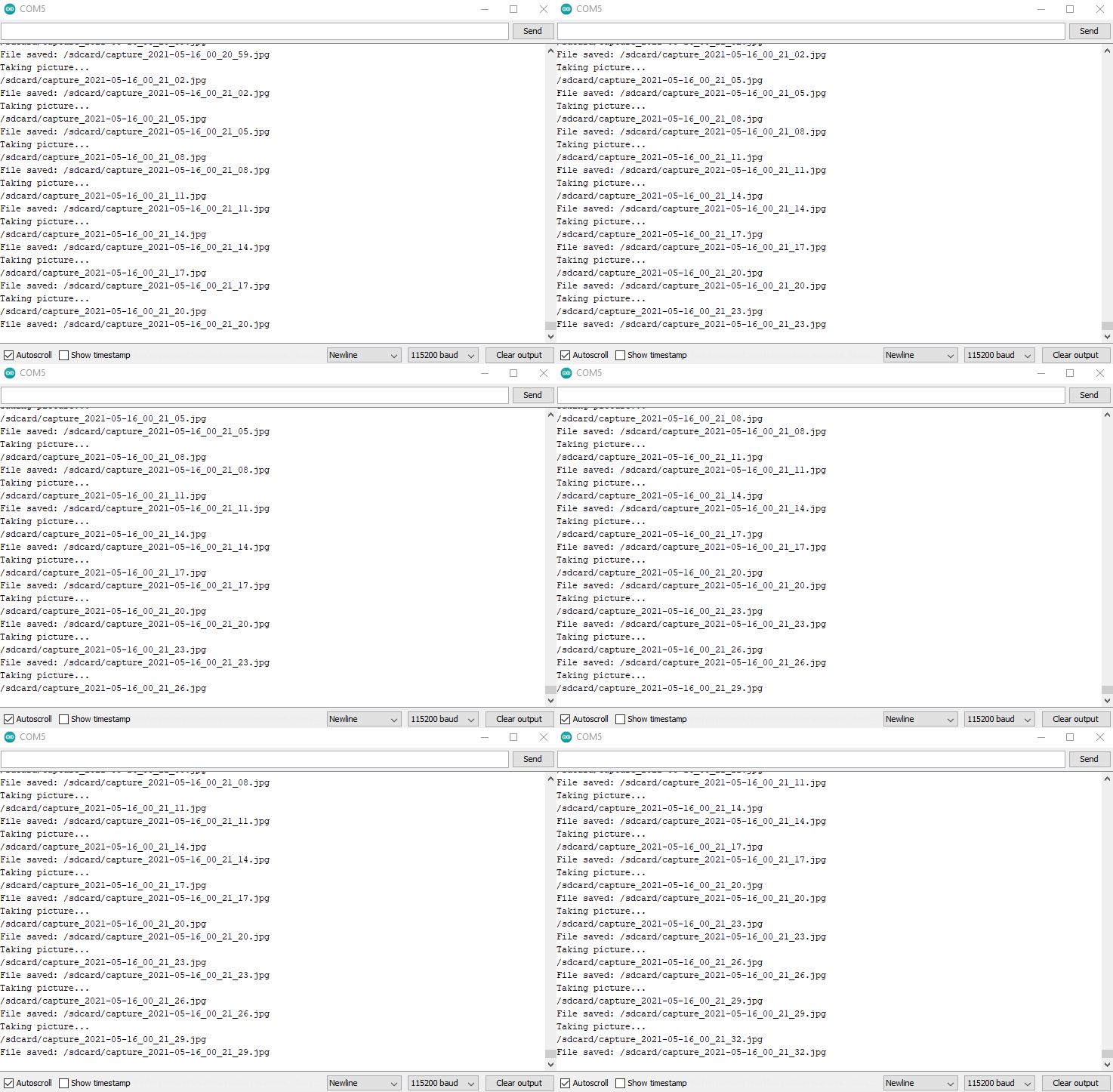
That’s it, If everything’s good, following output should come to your Serial Monitor.

Using an External Power Supply
ESP32 CAM requires 310mA and 5V if you’re using the flash LED as well. If not 180mA should work fine. This part really depends on how you want to power it up. You can use either batteris or AC currunt with a proper voltages and regulators in place.
In the ESP32 all ground pins should be connected together.
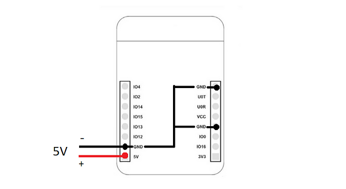
If you’re using a DC input, like a 9v battery, easiest way is to use a regulator to convert down to 5v, like the one below, using 7805 Voltage Regulator

If you are connecting it to AC currunt, use an AC to DC converter. You can build one your self or buy one for like $1 from an online store.

Try doing few more adjustments on your own. These are some basic solutions to the problems I faced. Hope it helped you too. 🖖
References:


